BOM: Business Organisation and Management (Australia and India) BOM: Board of Managers (defunct Alabama prison board) BOM: Bank of Montreal: BOM: Bureau Of Mines: BOM: By Other Means: BOM: Barrel of Monkeys: BOM: Bank of Mauritius (est. 1967) BOM: Business Object Model: BOM: Bank of Maharashtra: BOM: Back on the Market: BOM: Beginning Of.
Solidworks Electrical Bom


Bom Of Electrical Panel
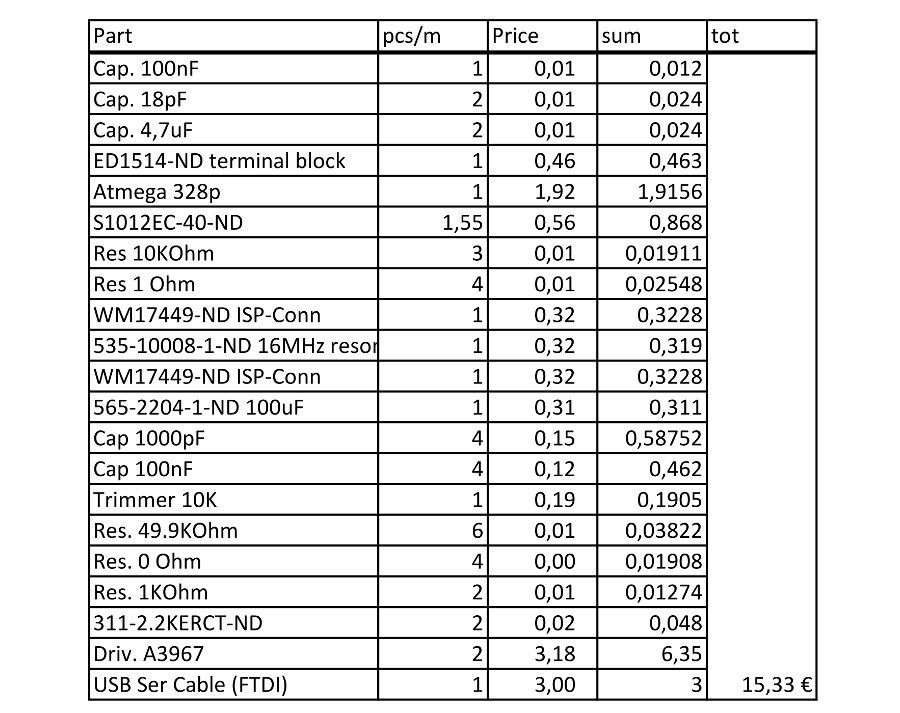
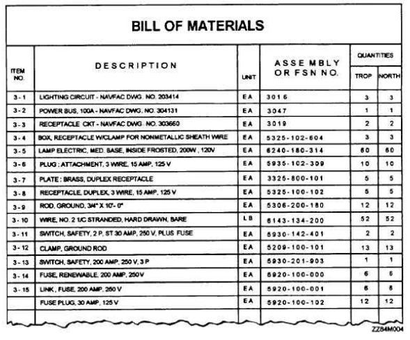
The engineering BOM is typically created by engineers using computer-aided design (CAD) or Electronic Design Automation (EDA). And for any given product design more than one EBOM may be created. For example, the BOM for the Printed Circuit Board Assembly (PCBA) designed by an electrical engineer lists the resistors, capacitors, and chips. It's typically best if the BOM reflects the assembly process. Start with the final product (or whatever goes in the box to be shipped) and work backwards through the subassembly. If the harness gets build on the final line, than only the parts (wire, crimps, etc.) should be in your BOM. If it shows up on the line pre-assembled, than it's a. Creating a combined Mechanical and Electrical Bill of Material. With mechanical and electrical design work often carried out by different individuals and with different systems, it’s difficult to create a single unified electro/mechanical bill of material (BOM). SOLIDWORKS Electrical 3D enables a single BOM to be created automatically within. For example, in the electronics industry, a typical BOM includes line items (rows of unique items) of all the electrical components and their quantities. Some of these (usually resistors and capacitors) can be swapped with alternative manufacturers on the fly if others are more readily available.
I spent many years designing circuit boards in a service bureau. I built assembly components, placed and routed traces, and created Gerber files and drawings. In all that time though, I never worked with a PCB bill of materials. It probably was because those customers created their own BOM’s and we worked only with the data that they gave us. Whatever the reason though, I was in the dark when it came to the BOM, and I had a lot of questions.
Since then, I’ve worked with plenty of BOM’s in the different jobs that I’ve had, and I usually don’t give them much thought anymore. So, I was surprised then when I recently found myself fielding questions about Bill of Materials. The most popular being, “what is a BOM and what it is used for?”. This got me thinking that maybe initial lack of BOM experience wasn’t uncommon. Perhaps there are many others out there who need some basic information on Printed Circuit Board BOMs.
If that describes you, then you’ve come to the right place and you're not alone.
The Basic Answer to “What is a BOM?”
The “Bill of Materials”, commonly referred to as the BOM, is simply a list. In the case of a PCB design, the bill of materials is a list of all the needed parts in the manufacturing process to build that specific printed circuit board.
A Printed Circuit Board is generated from PCB design software. In order to do this, the part information to generate the component must already be available in the CAD system. The information for each part is usually stored in its specific CAD part. As each part is instantiated in the design, the part information is pulled along with it from the BOM. Once in the design, the part information is then available for use in the different elements of the BOM.
What's Included in a Bill of Materials
There can be many types of information in a PCB BOM, but the parts must have a core set of elements to start with. Here is a list of some of the more core elements that you will see in a PCB BOM:
- Comment: Each part type on the Printed Circuit Board needs to have a unique identifier, or part number, listed as a comment in the bill of materials. Typically a company designated part number is used as the comment, but this is not a requirement. Vendor component part numbers or other designations can be used as instead. An example of a comment could be the company part number “27-0477-03”.
- Description: This is a basic description of the part. In the case of the comment 27-0477-03 listed above, the description could be “CAP 10uF 20% 6.3V”.
- Designator: Each of the individual components on the board will have its own unique reference designator. In the case of the 10uF capacitor, it could be “C27”.
- Footprint: This is the name of the physical CAD footprint used by the part. For instance, C27 could be using a CAD footprint named “CAP-1206”.
Usually the BOM is organized by comment with the other core elements that are associated with it are included next to it on the same line. As an example, let’s take the core element values from above and demonstrate a small one-line report:
Comment: Description: Designator: Footprint:
27-0477-03 CAP 10uF 20% 6.3V C19, C26, C27, C31, C46 CAP-1206
Depending on the requirements of the company, the BOM can also include additional elements of information. These can include tolerances, values, product structure, or any other type of information that is associated with the part like raw material notes. The only downside is that your report can get very long depending on the amount of elements that you include in it.
Advanced Uses for a Bill of Materials
Up to this point we have been talking about the basics of the BOM. There are also some more advanced features that we should mention as well. PCB BOM’s can be organized by elements other than the comments, and they can also be used to display some advance design data. Here are some examples:
Change the format of the BOM: You can change how your BOM looks by organizing it differently. Typically you will group the by the comment information, but you could also group it by footprint information instead.
Include components that are not fitted: You have the option to include parts that are designated as un-stuffed (not fitted) in the BOM.
Generate BOMs for different variants of the board: When you have created different stuffing options (fitted or not fitted) for parts in different variations of the board, you can generate different BOMs for those variants.

Does a BOM management tools that help your design and assembly departments work better together sound helpful? If so then Altium Designer’s BOM tools might be the answer that you are looking for. Find out more information by talking to an expert at Altium Designer.